Single-row four-point contact ball slewing bearing
September 29, 2018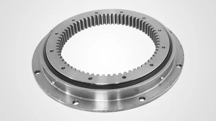
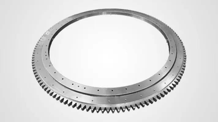
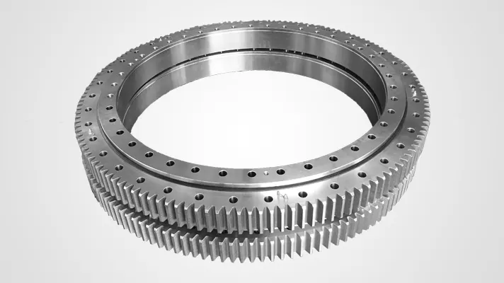

Light Series Slewing Bearing
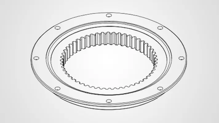
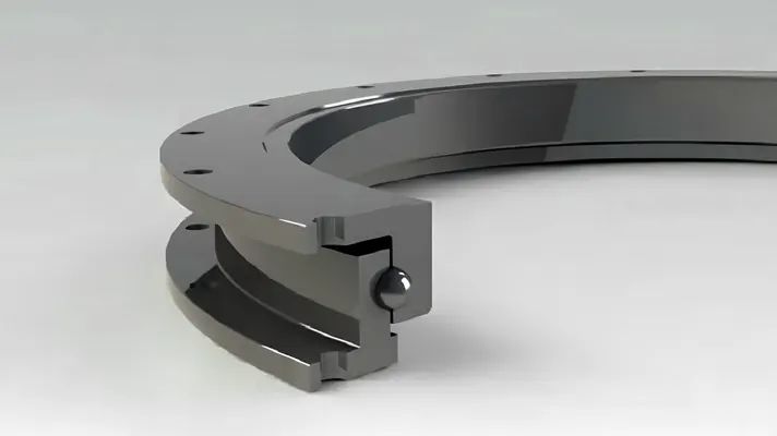
The light slewing bearing mainly includes the external ring & internal ring, the grease fittings, the sealing belt, the spacers, the load plug and the taper pin, the characteristics: the internal ring and the external ring are both L-shaped; The flank surface of ring is provided with a grease cup, steel balls is assembled between the external ring and internal ring on integration. each ball is separated by spacer, the steel balls and the spacers are installed through the load plug, and the taper pin to protect the ball running.
Note: The light slewing bearing mounting surface must meet the specified flatness and hardness. For special customized requirements, please contact my engineer. At the same time, we will provide a more comprehensive and targeted solution.

No gear
Light slewing bearings are engineered with a focus on compact design and reduced weight, making them ideal for applications where space constraints and weight considerations are crucial. Despite their lightweight construction, these bearings exhibit impressive load-carrying capacity, supporting axial, radial, and moment loads. Their precision and control make them suitable for applications requiring accurate and controlled rotational movement.
Note:
- n1 is No. of lube holes, the user can specify the lube hole position.
- n-φ can be changed to threading holes, hole diameter M, thread depth 2M.
- There are standard products in the catalog, and the inner and outer diameters are random tolerances. If there is a locating requirement for slewing bearing, please indicate the site and tolerance.
- It is standard type of our products, if you need more please contact with engineer.
Non Gear Drawing No . Raceway
center
distance Weight Outer
diameter Inner
diameter Total
height Outer
ring
mounting
hole Inner
ring
mounting
hole Mounting
hole
number Diameter
of
bolt
hole Mounting
hole
number Inner
ring
mounting
hole Inner
height
difference Outer
ring
height
difference Gear Module Tooth
no. Tooth
wide Normal
load Maximum
load Bearing
clearance DL
(mm)kg Da
(mm)Di
(mm)H
(mm)La
(mm)Li
(mm)na B/M
(mm)ni B/M
(mm)Hu
(mm)Ho
(mm)d
(mm)m
(mm)z b
(mm)(KN) (KN) axial
(mm)radial
(mm)230.20.0400.013
Graph⑤
Typ 21/520.0414 23.4 518 304 56 490 332 8 18 12 18 10.5 10.5 _ _ _ _ _ _ ≤0.5 ≤0.5 230.20.0500.013
Graph⑥
Typ 21/650.0544 31 648 434 56 620 462 10 18 14 18 10.5 10.5 _ _ _ _ _ _ ≤0.5 ≤0.5 230.20.0600.013
Graph⑦
Typ 21/750.0644 36.4 748 534 56 720 562 12 18 16 18 10.5 10.5 _ _ _ _ _ _ ≤0.5 ≤0.5 230.20.0700.013
Graph⑧
Typ 21/850.0744 42.8 848 634 56 820 662 12 18 16 18 10.5 10.5 _ _ _ _ _ _ ≤0.5 ≤0.5 230.20.0800.013
Graph⑨
Typ 21/950.0844 47.8 948 734 56 920 762 14 18 18 18 10.5 10.5 _ _ _ _ _ _ ≤0.5 ≤0.5 230.20.0900.013
Graph⑩
Typ 21/1050.0944 53.1 1048 834 56 1020 862 16 18 20 18 10.5 10.5 _ _ _ _ _ _ ≤0.5 ≤0.5 230.20.1000.013
Graph⑪
Typ 21/1200.01094 61.9 1198 984 56 1170 1012 16 18 20 18 10.5 10.5 _ _ _ _ _ _ ≤0.5 ≤0.5

External gear
External Gear Drawing No . Raceway
center
distance Weight Outer
diameter Inner
diameter Total
height Outer
ring
mounting
hole Inner
ring
mounting
hole Mounting
hole
number Diameter
of
bolt
hole Mounting
hole
number Inner
ring
mounting
hole Inner
height
difference Outer
ring
height
difference Gear Module Tooth
no. Tooth
wide Normal
load Maximum
load DL
(mm)kg Da
(mm)Di
(mm)H
(mm)La
(mm)Li
(mm)na B/M
(mm)ni B/M
(mm)Hu
(mm)Ho
(mm)d
(mm)m
(mm)z b
(mm)(KN) (KN) 231.20.0400.013
Graph⑤
Typ 21/520.1414 29.3 504 304 56 455 332 10 M12 12 18 10.5 _ 495 5 99 45.5 11.75 23.5 231.20.0500.013
Graph⑥
Typ 21/650.1544 39.5 640.8 434 56 585 462 14 M12 14 18 10.5 _ 630 6 105 45.5 14.2 28.4 231.20.0600.013
Graph⑦
Typ 21/750.1644 47.6 742.8 534 56 685 562 16 M12 16 18 10.5 _ 732 6 122 45.5 14.2 28.4 231.20.0700.013
Graph⑧
Typ 21/850.1744 53.5 838.8 634 56 785 662 18 M12 16 18 10.5 _ 828 6 138 45.5 18.93 37.86 231.20.0800.013
Graph⑨
Typ 21/950.1844 65.1 950.4 734 56 885 762 18 M12 18 18 10.5 _ 936 8 117 45.5 18.93 37.86 231.20.0900.013
Graph⑩
Typ 21/1050.1944 69.6 1046.4 834 56 985 862 20 M12 20 18 10.5 _ 1032 8 129 45.5 18.93 37.86 231.20.1000.013
Graph⑪
Typ 21/1200.11094 83 1198.4 984 56 1135 1012 22 M12 20 18 10.5 _ 1184 8 148 45.5 18.93 37.86

Internal gear
Internal Gear Drawing No . Raceway
center
distance Weight Outer
diameter Inner
diameter Total
height Outer
ring
mounting
hole Inner
ring
mounting
hole Mounting
hole
number Diameter
of
bolt
hole Mounting
hole
number Inner
ring
mounting
hole Inner
height
difference Outer
ring
height
difference Gear Module Tooth
no. Tooth
wide Normal
load Maximum
load Bearing
clearance DL
(mm)kg Da
(mm)Di
(mm)H
(mm)La
(mm)Li
(mm)na B/M
(mm)ni B/M
(mm)Hu
(mm)Ho
(mm)d
(mm)m
(mm)z b
(mm)(KN) (KN) axial
(mm)radial
(mm)232.20.0400.013
Graph⑤
Typ 21/520.2414 27.1 518 326.5 56 490 375 8 18 12 M12 10.5 _ 335 5 67 45.5 13.54 27.08 ≤0.5 ≤0.5 232.20.0500.013
Graph⑥
Typ 21/650.2544 36.9 648 445.2 56 620 505 10 18 16 M12 10.5 _ 456 6 76 45.5 16 32 ≤0.5 ≤0.5 232.20.0600.013
Graph⑦
Typ 21/750.2644 43.7 748 547.2 56 720 605 12 18 18 M12 10.5 _ 558 6 93 45.5 15.62 31.24 ≤0.5 ≤0.5 232.20.0700.013
Graph⑧
Typ 21/850.2744 51.1 848 649.2 56 820 705 12 18 20 M12 10.5 _ 660 6 110 45.5 15.32 30.64 ≤0.5 ≤0.5 232.20.0800.013
Graph⑨
Typ 21/950.2844 61.6 948 737.6 56 920 805 14 18 20 M12 10.5 _ 752 8 94 45.5 20.8 41.6 ≤0.5 ≤0.5 232.20.0900.013
Graph⑩
Typ 21/1050.2944 65.8 1048 841.6 56 1020 905 16 18 22 M12 10.5 _ 856 8 107 45.5 20.49 40.98 ≤0.5 ≤0.5 232.20.1000.013
Graph⑪
Typ 21/1200.21094 80.7 1198 985.6 56 1170 1055 16 18 24 M12 10.5 _ 1000 8 125 45.5 20.16 40.32 ≤0.5 ≤0.5